
Servicing XTx00 RGA Probes, SN 1000+
Ionizer/Dual Filament Replacement
The filament will eventually fail after years of operation even in a clean UHV system due to the thoria coating on it eventually decomposing and evaporating. The Extorr RGA uses two thoria coated iridium filaments that operate in parallel. When 1 of them burns out, the other will continue to operate the instrument normally, giving a warning so that the user will be able to replace the filament assembly when it is convenient. Unlike other RGA’s the Extorr filament will not fail due to exposure to very high pressures because it is protected by the pirani gauge output. A complete filament failure can be verified by looking at the DIAGNOSTICS readings on the OUTPUTS page. If there is an open filament, the filament voltage will read > 5 volts and there will be < .1 amp filament current. The filament light icon will not stay yellow on the main window. If only one of the filaments is burned out, the instrument will operate normally but there will be <1.5 amp of filament current.
The ionizer normally will last for years without attention in a UHV environment, there is nothing to wear out, but the metal surfaces can become contaminated. The results of contamination could cause low sensitivity for partial pressure readings. It generally take a very severe contamination to cause the total pressure readings to be low because the B/A type gauge uses higher voltages and works with more energetic ions that are less susceptible to stray fields. If you have a total pressure reading of 10-7 for example, your partial pressure readings should add up to about that. A number of factors such as the relative sensitivities of different compounds and the cracking of molecules into fragments in the ionizer makes it unlikely that they will add up exactly, but as the ionizer contamination increases, you may see a an order of magnitude or more difference between the total pressure and the sum of partial pressures. Cleaning the ionizer is difficult if not impossible in most cases, so replacement is the remedy. It is also likely that some contamination will make it to the rods of the quadrupole, as a direct result of the principle of operation of this type of analyzer. So when replacing the ionizer due to low sensitivity, it is a good idea to clean the quadrupole rods also.
Always handle the probe with clean gloves, or you will see the results of your contamination on the next scan. A fingerprint will outgas and cause peaks at virtually every amu until it is evaporated or turned into low vapor pressure compounds in your vacuum system. Of course other sources of contamination such as diffusion or mechanical pump oil could cause similar problems. Even after the volatiles are gone, the residue may cause the probe to operate improperly by leaving behind insulating compounds, or high secondary electron yielding surfaces where there is contamination. This can cause charge from electrons to build up on these insulators and disturb the electric fields in the ionizer or the mass filter leading to low sensitivity.
At the factory, all parts are mechanically cleaned, then vacuum baked, and then plasma cleaned. If you are doing UHV work and demand the best cleanliness, you can send the analyzer to the factory for refurbishment, but many customers have had good success with the following method. The rods are best cleaned with an abrasive method, such as 1200 grit abrasive paper polishing, followed by an Alconox ultrasonic bath and several rinses with distilled water. The Extorr probe was designed to allow easy cleaning and ionizer/filament replacement, the only tool required is an allen wrench to loosen the set screws that hold the ionizer to the probe. This is supplied with all new ionizers.
The following steps will restore the XT system to proper operation:
click to enlarge pictures
Step 1
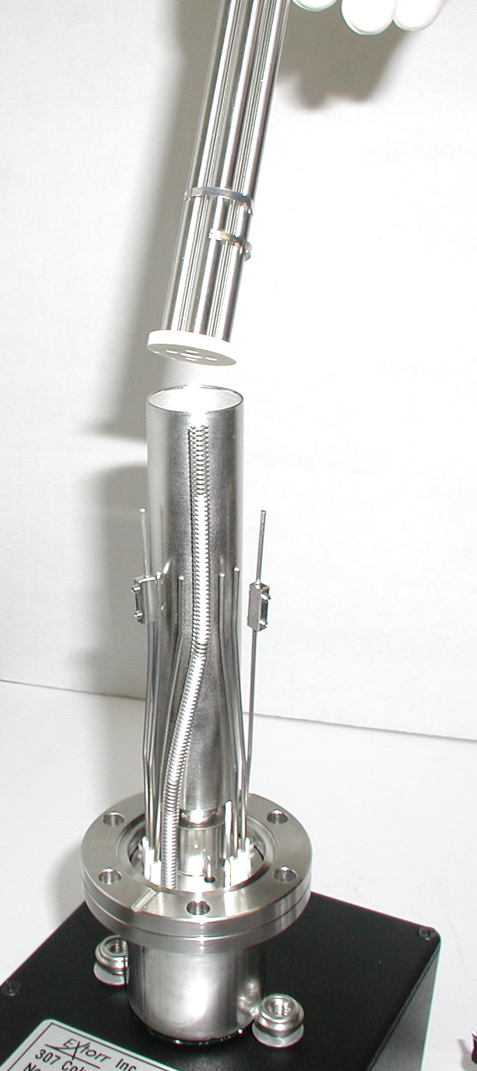
Placing the analyzer onto the CCU without the thumbscrews makes a good stand for the repair. Loosen the top set screws on the 2 barrel connectors that connect the filament wires. Remove and discard the old filament assembly. If you are only replacing the filament, skip to step 7.
Step 2
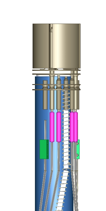
Loosen the bottom set screws on each barrel connector and slide them down the wires towards the feedthrough.
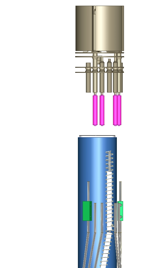
Remove the ionizer by pulling upward, a gentle twisting action may be necessary.
Step 3
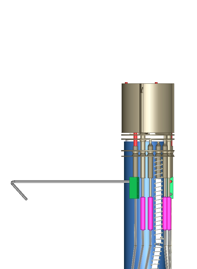
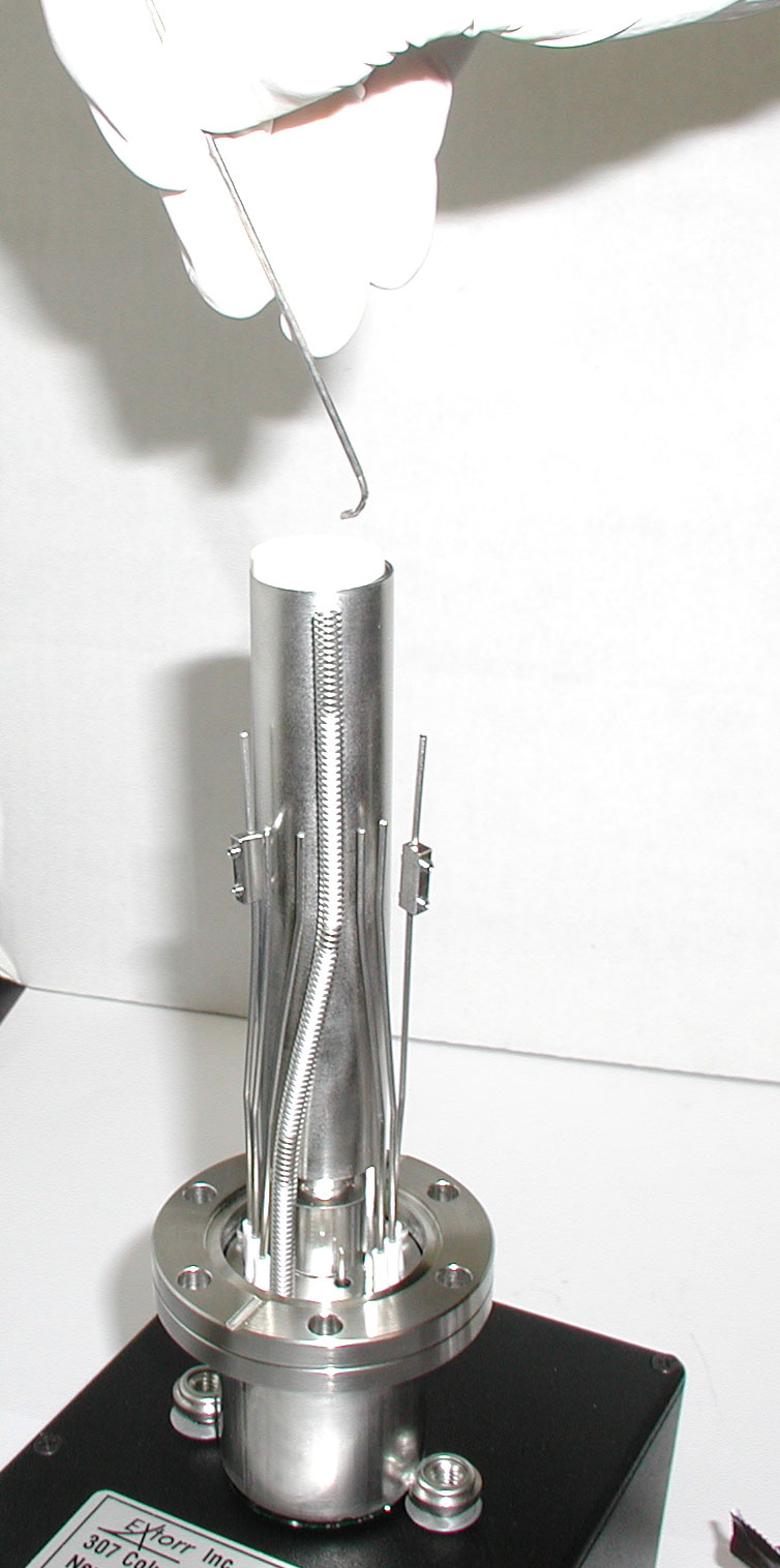
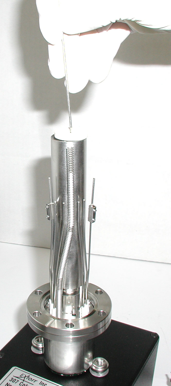
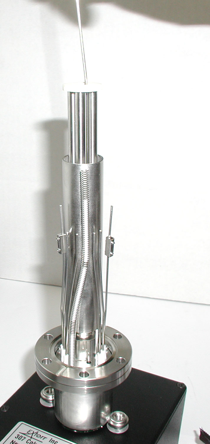
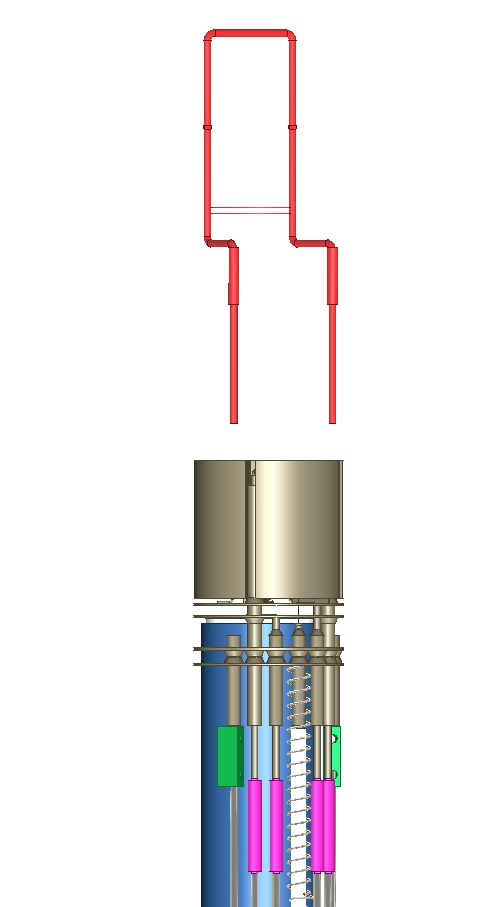
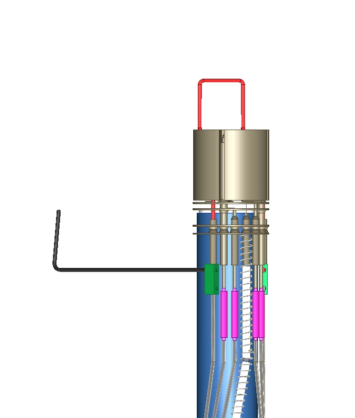
Using a hook made from some .062 diameter wire, pull the mass filter out of the frame.
Step 4
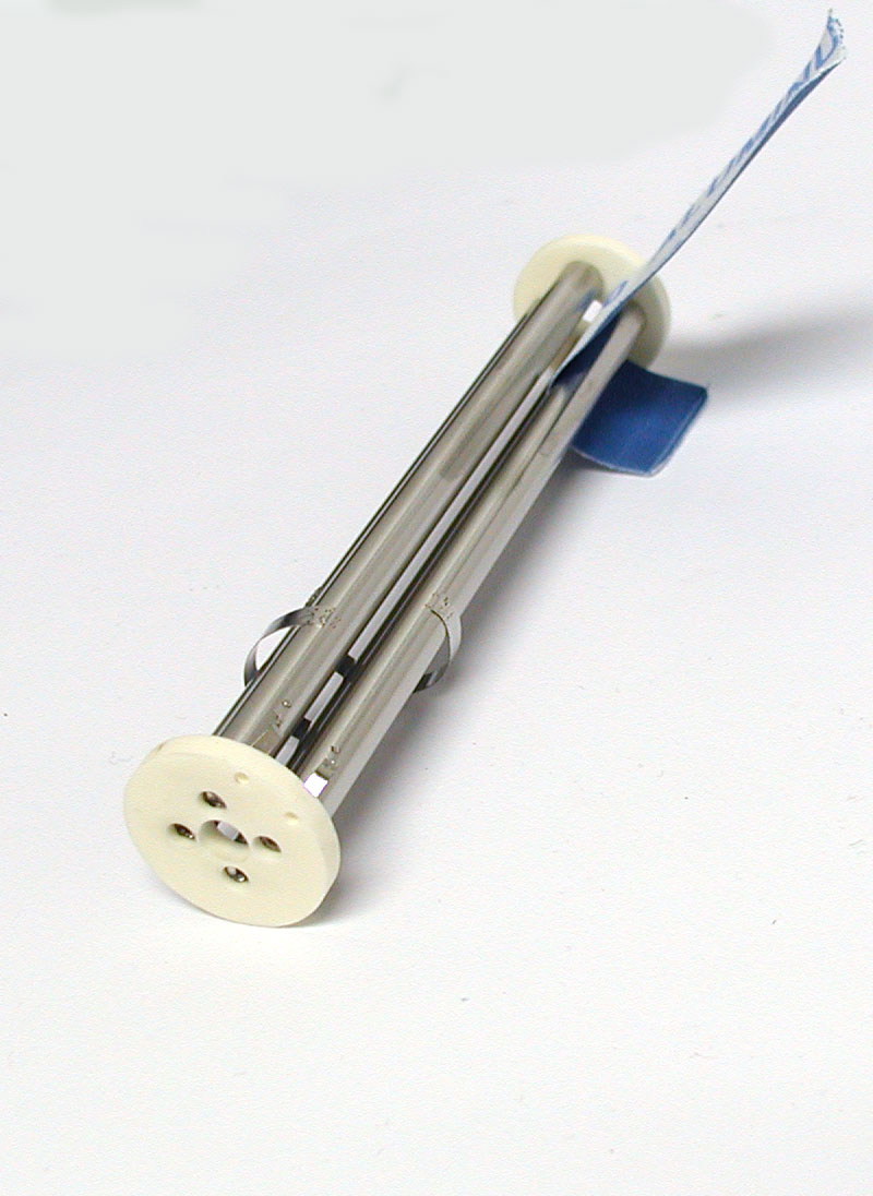
Clean the surfaces of the rods with 1200 grit alumina abrasive paper until they are bright. Using a waterproof paper with water works well. Be careful not to bend the electrical contacts. Then clean in Alconox detergent using an ultrasonic cleaner at 40 kHz. Rinse well with distilled water in the ultrasonic bath several times, then dry at 75 degrees C.
Step 5
Next insert the mass filter into the probe, being careful to line up the 2 wires with the two holes in the end of the mass filter that make the electrical contact.
Step 6
Using a small pair of needle nose pliers or a strong pair of tweezers, remove the 4 tubular spring connectors from the old ionizer and push them onto the respective pins on the new ionizer. push the new ionizer down onto the probe, carefully engaging the center pin and BA shield spring until the focus plate on the ionizer is flush with the top of the mass filter ceramic end.
Step 7
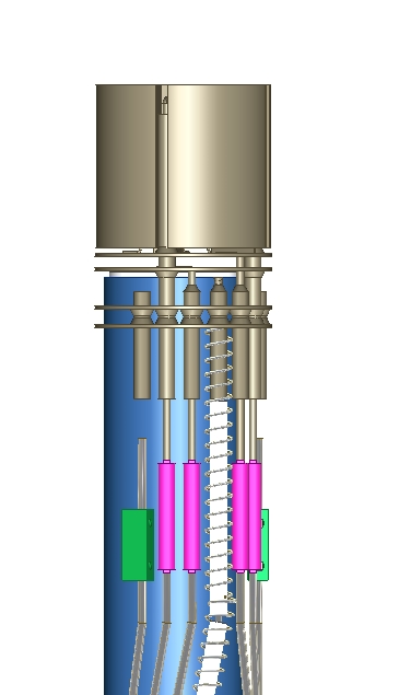
Slide the four 4 tubular spring connectors down to engage the respective feedthrough wires.
Insert the new filament assembly and while holding down on the filament, slide the barrel connectors into place and tighten both set screws on each barrel connector.
Be careful that the wires do not short to each other or the frame. You can bend the wires from the feedthrough easily if necessary, but do not bend the wires from the ionizer or you may crack the ceramics.
Step 8
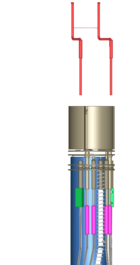
Finally, break off the top of the filament assembly and discard.